- 您现在的位置:买卖IC网 > Sheet目录887 > UCH-15/6.7-D48NB-C (Murata Power Solutions Inc)CONV DC/DC 100.5W 15V 6.7A
�� �
�
�Single� Output� UCH� Models�
�Isolated,� “Half-Brick”�
�1.8?15V� Output� DC/DC� Converters�
�TECHNICAL� NOTES�
�Input� Fusing�
�Certain� applications� and/or� safety� agencies� may� require� fuses� at� the� inputs� of�
�power� conversion� components.� Fuses� should� also� be� used� when� there� is� the�
�possibility� of� sustained� input� voltage� reversal� which� is� not� current-limited.� For�
�greatest� safety,� we� recommend� a� fast� blow� fuse� installed� in� the� ungrounded�
�input� supply� line.�
�The� installer� must� observe� all� relevant� safety� standards� and� regulations.� For�
�safety� agency� approvals,� install� the� converter� in� compliance� with� the� end-user�
�safety� standard,� i.e.� IEC/EN/UL� 60950-1.�
�Input� Reverse-Polarity� Protection�
�If� the� input� voltage� polarity� is� reversed,� an� internal� body� diode� will� become�
�forward� biased� and� likely� draw� excessive� current� from� the� power� source.� If� this�
�source� is� not� current-limited� or� the� circuit� appropriately� fused,� it� could� cause�
�permanent� damage� to� the� converter.� Please be sure to install a properly-�
�rated external input fuse� (see� Speci?cations).�
�Input� Under-Voltage� Shutdown� and� Start-Up� Threshold�
�Under� normal� start-up� conditions,� converters� will� not� begin� to� regulate� properly�
�until� the� ramping-up� input� voltage� exceeds� and� remains� at� the� Start-Up�
�Threshold� Voltage� (see� Speci?cations).� Once� operating,� converters� will� not�
�turn� off� until� the� input� voltage� drops� below� the� Under-Voltage� Shutdown� Limit.�
�Subsequent� restart� will� not� occur� until� the� input� voltage� rises� again� above� the�
�Start-Up� Threshold.� This� built-in� hysteresis� prevents� any� unstable� on/off� opera-�
�tion� at� a� single� input� voltage.�
�Users� should� be� aware� however� of� input� sources� near� the� Under-Voltage�
�Shutdown� whose� voltage� decays� as� input� current� is� consumed� (such� as� ca-�
�Input� Source� Impedance�
�These� converters� will� operate� to� speci?cations� without� external� components,�
�assuming� that� the� source� voltage� has� very� low� impedance� and� reasonable� in-�
�put� voltage� regulation.� Since� real-world� voltage� sources� have� ?nite� impedance,�
�performance� is� improved� by� adding� external� ?lter� components.� Sometimes� only�
�a� small� ceramic� capacitor� is� suf?cient.� Since� it� is� dif?cult� to� totally� characterize�
�all� applications,� some� experimentation� may� be� needed.� Note� that� external� input�
�capacitors� must� accept� high� speed� switching� currents.�
�Because� of� the� switching� nature� of� DC/DC� converters,� the� input� of� these�
�converters� must� be� driven� from� a� source� with� both� low� AC� impedance� and�
�adequate� DC� input� regulation.� Performance� will� degrade� with� increasing� input�
�inductance.� Excessive� input� inductance� may� inhibit� operation.� The� DC� input�
�regulation� speci?es� that� the� input� voltage,� once� operating,� must� never� degrade�
�below� the� Shut-Down� Threshold� under� all� load� conditions.� Be� sure� to� use�
�adequate� trace� sizes� and� mount� components� close� to� the� converter.�
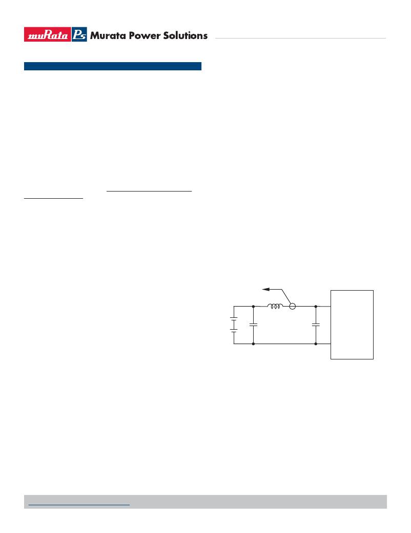
�I/O� Filtering,� Input� Ripple� Current� and� Output� Noise�
�All� models� in� this� converter� series� are� tested� and� speci?ed� for� input� re?ected�
�ripple� current� and� output� noise� using� designated� external� input/output� compo-�
�nents,� circuits� and� layout� as� shown� in� the� ?gures� below.� External� input� capaci-�
�tors� (Cin� in� the� ?gure)� serve� primarily� as� energy� storage� elements,� minimizing�
�line� voltage� variations� caused� by� transient� IR� drops� in� the� input� conductors.�
�Users� should� select� input� capacitors� for� bulk� capacitance� (at� appropriate�
�frequencies),� low� ESR� and� high� RMS� ripple� current� ratings.� In� the� ?gure� below,�
�the� Cbus� and� Lbus� components� simulate� a� typical� DC� voltage� bus.� Your� speci?c�
�system� con?guration� may� require� additional� considerations.� Please� note� that�
�the� values� of� Cin,� Lbus� and� Cbus� will� vary� according� to� the� speci?c� converter�
�model.�
�pacitor� inputs),� the� converter� shuts� off� and� then� restarts� as� the� external� capaci-�
�tor� recharges.� Such� situations� could� oscillate.� To� prevent� this,� make� sure� the�
�operating� input� voltage� is� well� above� the� UV� Shutdown� voltage� AT� ALL� TIMES.�
�TO�
�OSCILLOSCOPE�
�CURRENT�
�PROBE�
�+VIN�
�Start-Up� Time�
�Assuming� that� the� output� current� is� set� at� the� rated� maximum,� the� Vin� to� Vout�
�V� IN�
�+�
�–�
�+�
�C� BUS�
�L� BUS�
�C� IN�
�Start-Up� Time� (see� Speci?cations)� is� the� time� interval� between� the� point� when�
�the� ramping� input� voltage� crosses� the� Start-Up� Threshold� and� the� fully� loaded�
�regulated� output� voltage� enters� and� remains� within� its� speci?ed� accuracy� band.�
�Actual� measured� times� will� vary� with� input� source� impedance,� external� input�
�capacitance,� input� voltage� slew� rate� and� ?nal� value� of� the� input� voltage� as� it�
�appears� at� the� converter.�
�These� converters� include� a� soft� start� circuit� to� moderate� the� duty� cycle� of� its�
�PWM� controller� at� power� up,� thereby� limiting� the� input� inrush� current.�
�The� On/Off� Remote� Control� interval� from� On� command� to� Vout� regulated�
�assumes� that� the� converter� already� has� its� input� voltage� stabilized� above� the�
�Start-Up� Threshold� before� the� On� command.� The� interval� is� measured� from� the�
�On� command� until� the� output� enters� and� remains� within� its� speci?ed� accuracy�
�band.� The� speci?cation� assumes� that� the� output� is� fully� loaded� at� maximum�
�rated� current.� Similar� conditions� apply� to� the� On� to� Vout� regulated� speci?cation�
�such� as� external� load� capacitance� and� soft� start� circuitry.�
�–�
�?VIN�
�C� IN� =� 33μF,� ESR� <� 700mΩ� @� 100kHz�
�C� BUS� =� 220μF,� ESR� <� 100mΩ� @� 100kHz�
�L� BUS� =� 12μH�
�Figure� 2.� Measuring� Input� Ripple� Current�
�In� critical� applications,� output� ripple� and� noise� (also� referred� to� as� periodic�
�and� random� deviations� or� PARD)� may� be� reduced� by� adding� ?lter� elements�
�such� as� multiple� external� capacitors.� Be� sure� to� calculate� component� tempera-�
�ture� rise� from� re?ected� AC� current� dissipated� inside� capacitor� ESR.�
�In� the� ?gure,� the� two� copper� strips� simulate� real-world� printed� circuit�
�impedances� between� the� power� supply� and� its� load.� In� order� to� minimize� circuit�
�errors� and� standardize� tests� between� units,� scope� measurements� should� be�
�made� using� BNC� connectors� or� the� probe� ground� should� not� exceed� one� half�
�inch� and� soldered� directly� to� the� ?xture.�
�www.murata-ps.com/support�
�MDC_UCH� Models.C01� Page� 14� of� 18�
�发布紧急采购,3分钟左右您将得到回复。
相关PDF资料
UCJ1V101MCL1GS
CAP ALUM 100UF 35V 20% SMD
UCL1V151MNL1GS
CAP ALUM 150UF 35V 20% SMD
UCS2E330MHD1TO
CAP ALUM 33UF 250V 20% RADIAL
UCW1V331MNL1GS
CAP ALUM 330UF 35V 20% SMD
UCY2V120MPD
CAP ALUM 12UF 350V 20% RADIAL
UCZ1E331MCL1GS
CAP ALUM 330UF 25V 20% SMD
UDB1H150MHM
CAP ALUM 15UF 50V 20% RADIAL
UEE-3.3/30-D48PB-C
36-75VIN 3.3VOUT 99W POS LOGIC
相关代理商/技术参数
UCH-15/6.7-D48NB-C
制造商:Murata Power Solutions 功能描述:DC/DC Converter
UCH-15/6.7-D48N-C
功能描述:DC/DC转换器 15Vout 6.7A 100.5W 48Vin Neg Polarity
RoHS:否 制造商:Murata 产品: 输出功率: 输入电压范围:3.6 V to 5.5 V 输入电压(标称): 输出端数量:1 输出电压(通道 1):3.3 V 输出电流(通道 1):600 mA 输出电压(通道 2): 输出电流(通道 2): 安装风格:SMD/SMT 封装 / 箱体尺寸:
UCH-15/6.7-D48PB-C
功能描述:DC/DC转换器 48V 15Vot 6.7A100.5W pos polrty w/Baseplt RoHS:否 制造商:Murata 产品: 输出功率: 输入电压范围:3.6 V to 5.5 V 输入电压(标称): 输出端数量:1 输出电压(通道 1):3.3 V 输出电流(通道 1):600 mA 输出电压(通道 2): 输出电流(通道 2): 安装风格:SMD/SMT 封装 / 箱体尺寸:
UCH-15/6.7-D48P-C
功能描述:DC/DC转换器 48V 15Vot 6.7A100.5W positive polarity RoHS:否 制造商:Murata 产品: 输出功率: 输入电压范围:3.6 V to 5.5 V 输入电压(标称): 输出端数量:1 输出电压(通道 1):3.3 V 输出电流(通道 1):600 mA 输出电压(通道 2): 输出电流(通道 2): 安装风格:SMD/SMT 封装 / 箱体尺寸:
UCH1V101MCL1GS
功能描述:100μF 35V Aluminum Capacitors Radial, Can - SMD 300 mOhm @ 100kHz 2000 Hrs @ 125°C 制造商:nichicon 系列:UCH 包装:剪切带(CT) 零件状态:有效 电容:100μF 容差:±20% 额定电压:35V ESR(等效串联电阻):300 毫欧 @ 100kHz 不同温度时的使用寿命:125°C 时为 2000 小时 工作温度:-40°C ~ 125°C 极化:极化 应用:通用 纹波电流:98.5mA @ 120Hz 阻抗:- 引线间距:- 大小/尺寸:0.248" 直径(6.30mm) 高度 - 安装(最大值):0.315"(8.00mm) 表面贴装焊盘尺寸:0.260" 长 x 0.260" 宽(6.60mm x 6.60mm) 安装类型:表面贴装 封装/外壳:径向,Can - SMD 标准包装:1
UCH1V221MCL1GS
功能描述:CAP ALUM 220UF 20% 35V SMD 制造商:nichicon 系列:UCH 包装:剪切带(CT) 零件状态:在售 电容:220μF 容差:±20% 电压 - 额定:35V ESR(等效串联电阻):200 毫欧 @ 100kHz 不同温度时的使用寿命:125°C 时为 2000 小时 工作温度:-40°C ~ 125°C 极化:极化 等级:- 应用:通用 Ripple Current:135mA @ 120Hz Ripple Current @ High Frequency:270mA @ 100kHz 引线间距:- 大小/尺寸:0.315" 直径(8.00mm) 高度 - 安装(最大值):0.425"(10.80mm) 表面贴装焊盘尺寸:0.327" 长 x 0.327" 宽(8.30mm x 8.30mm) 安装类型:表面贴装 封装/外壳:径向,Can - SMD 标准包装:1
UCH1V331MCL1GS
功能描述:35V 330UF 20% HIGH RELIABILITY-S 制造商:nichicon 系列:UCH 包装:剪切带(CT) 零件状态:在售 电容:330μF 容差:±20% 电压 - 额定:35V ESR(等效串联电阻):150 毫欧 @ 100kHz 不同温度时的使用寿命:125°C 时为 2000 小时 工作温度:-40°C ~ 125°C 极化:极化 等级:- 应用:通用 Ripple Current:250mA @ 120Hz Ripple Current @ High Frequency:500mA @ 100kHz 引线间距:- 大小/尺寸:0.394" 直径(10.00mm) 高度 - 安装(最大值):0.425"(10.80mm) 表面贴装焊盘尺寸:0.406" 长 x 0.406" 宽(10.30mm x 10.30mm) 安装类型:表面贴装 封装/外壳:径向,Can - SMD 标准包装:1
UCH1V470MCL1GS
功能描述:47μF 35V Aluminum Capacitors Radial, Can - SMD 300 mOhm @ 100kHz 2000 Hrs @ 125°C 制造商:nichicon 系列:UCH 包装:剪切带(CT) 零件状态:有效 电容:47μF 容差:±20% 额定电压:35V ESR(等效串联电阻):300 毫欧 @ 100kHz 不同温度时的使用寿命:125°C 时为 2000 小时 工作温度:-40°C ~ 125°C 极化:极化 应用:通用 纹波电流:98.5mA @ 120Hz 阻抗:- 引线间距:- 大小/尺寸:0.248" 直径(6.30mm) 高度 - 安装(最大值):0.315"(8.00mm) 表面贴装焊盘尺寸:0.260" 长 x 0.260" 宽(6.60mm x 6.60mm) 安装类型:表面贴装 封装/外壳:径向,Can - SMD 标准包装:1